The start wasn’t trivial at all. You could think that since GPUs have been around for a few decades it would be easy to communicate with them? Not in the slightest. For one, as specialized hardware they demand you feed them data as they want them, second, there are a number of competing APIs to choose from. And that is just the tip of the iceberg.
Everything you see here took me a solid two weeks of work at least, not counting the research, granted I had very little idea what I was getting myself into.
Not going to go into the details of everything, because this first part will last forever and there are books and tutorials out there. These tutorials, resources will be linked where appropriate. Only the ideas that I haven’t seen elsewhere, that helped me out a lot will be pointed out here.
The API
There are a number of APIs to choose from.
DirectX and Metal
Both are platform dependent. DirectX for Microsoft products and Metal for Apple, thus they do not fit the criteria of our engine.
OpenGL
The legendary platform independent old goat. Windows, Linux, Mac and with its WebGL it also supports the web. Primarily implemented using C/C++ it is a battle tested, performant API. Starting to work with it though makes little sense as it is actively being superseded by the Vulkan.
Vulkan
The new generation of cross-platform APIs, similarly developed by the Khronos Group just like OpenGL. It supports all new fancy rendering pipelines, like raytracing and it is extremely performant and configurable. This comes with a price though. The barrier to entry is very high and a simple hello world of the GPU world of drawing a single triangle to the screen takes about a thousand line of code. Primarily using C++ it is extremely performant, but as mentioned complex. While it has been around for a while now and some games actively use it/support it, while engines are implementing support for it, in many cases the drivers seem to be less stable for it.
For example Doom 2016 and Doom Eternal where the only two games that I have tested so far that worked flawlessly with the Vulkan API. All others seem to have one problem or another with their implementation. This is to be expected to some extent but at the time of writing we are already in 2026 and issues still persist. The adoption is a little bit slow, not entirely sure what the reason may be. The API with a good engine is definitely extremely performant. The above mentioned two examples run much better on Vulkan than they did on DirectX.
Nevertheless, as a start I won’t be starting out with Vulkan. Too complex for a complete beginner, and we will see there are daemons aplenty to tackle. Likely in the future, when other issues have been ironed out, support for Vulkan will be added as well.
WebGPU
A cross-platform API, primarily developed for the web as a replacement for WebGL, by the World Wide Web Consortium W3C. It is a lot more simplistic than Vulkan and has native implementation both in Rust and C++. Likely, making it performant enough for our investigative purposes. If and when needed, we can always switch to Vulkan, but that point is probably far away.
In this case the Rust based wgpu library was used.
The basics
Setting up the pipeline
To set up a basic WebGPU based rendering pipeline the WebGPU Fundamentals tutorial has been used. It walks you through the basic concepts of what must be done while communicating with the GPU, what certain terms mean and how can be used. This is a little bit complicated, and likely can be much more complicated still. I don’t intend to pretend to understand what and why is exactly happening, so won’t try and explain it either. Books like Real-Time Rendering - Fourth Edition go into some details but not all. For the window handling the winit library was used.
What we need to know is that the GPU is a specialized hardware. It mostly wants to draw. We don’t communicate with it directly (probably because it would be a nightmare similar to trying to write instructions directly for each CPU architecture), rather through these APIs. These APIs impose on us a few requirements, like which shading language we can use, what form the data needs to have, what memory alignment should be used for each type, how some transformation matrices should behave. Following these isn’t trivial but not particularly difficult either.
The result is quite interesting. You configure the render pipeline, prepare the data in the appropriate format, which is nothing but a stream of bytes, with some attached data structures describing how big a single unit it. However, nowhere is it specified what is actually inside the data, that will only be known by the GPU when the appropriate shader code has been matched with the appropriate buffer.
For example on the GPU side I use some Globals variable, which don’t change within a render pass:
struct Globals {
    view_projection: mat4x4f,
    light_color: vec4f,
    light_position: vec3f,
    view_world_position: vec3f,
    shininess: f32,
    light_direction: vec3f,
    limit: f32,
};
And this is how it becomes actually accessible:
@group(0)
@binding(0)
var<uniform> global: Globals;
What this tells to the GPU is that on bind group 0 at binding location 0 it will find
a chunk of data that can be interpreted as something defined in the Globals struct.
It is not entirely clear to me how to best think of bind groups and bindings, but it seems like
a structured description of a given memory location which resides on the GPU.
On the CPU side this data is mostly just a stream of bytes, most of the values being hardcoded as well.
A small snippet form the beginning:
let global_uniforms = view_projection_matrix
    .as_slices()
    .iter()
    .flatten()
    .flat_map(|entry| entry.to_le_bytes())
    .chain(
        // light color
        [0.2f32, 1.0, 0.2, 1.0]
            .iter()
            .flat_map(|entry| entry.to_le_bytes()),
    )
    .chain(
        // light position
        // last value is padding
        [-10.0f32, 10.0, 10.0, 0.0]
            .iter()
            .flat_map(|entry| entry.to_le_bytes()),
    )
    .chain( ...
Notice in case of the light_position we have to add another floating point value, because WebGPU
demands that vec3f types be padded to 16 bytes even though they are only 12 bytes long.
Somehow I find this a rather fascinating solution for defining a mapping between two different worlds.
The GPU doesn’t know, doesn’t care about how the data looks somewhere else. Give it a location to
read from, tell it what it should expect, provide it as a stream of bytes (types are completely lost),
and it will handle the rest.
I wonder if internally no types are actually ever created and the shader language is nothing, but
something to help the developer comprehend what is happening, while the GPU is directly working with
bytes through some arcane hardware/API magic.
Of course, this is not the most optimal way of doing this, but it highlights one important aspect of the GPU’s internal behavior and the goal was to understand what is happening. For this reason putting the byte sequence together by hand was the clearest choice.
Apart from the byte muckery what proved to be problematic in the beginning was the coordinate systems.
Coordinate system
There are mainly two coordinate systems used today. Right and left handed.
In both cases the Y vector is pointing up, the Z vector is pointing towards you.
For the right handed system the X vector will be pointing right, while in the left it will point
to the left.
You can always easily remember which one is which if you use your hands where the thumb, index and middle
finger will always represent the: X, Y and Z axis.
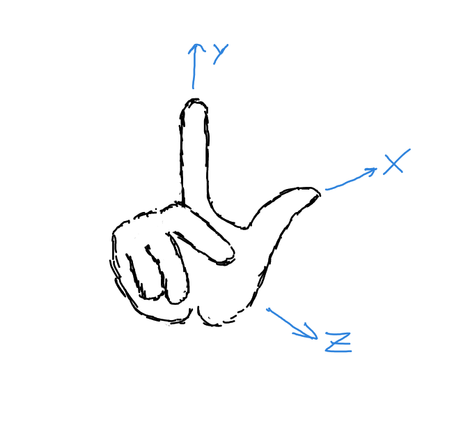
Right handed Y up coordinate system
Now why is the Y vector up and the Z pointing towards you? That I do not know. Probably, someone had to
choose something in the beginning and it made sense.
I would venture that because in 2D Cartesian coordinate system X is the horizontal axis increasing to the right,
and Y is the vertical increasing upwards, it nicely extends to 3D using the right hand rule with Z
increasing towards you.
In truth though Y doesn’t have to be up. In some engines like Unreal Engine,
CryEngine the Z vector is up. They also mix handedness. Unreal uses the left-handed
order while CryEngine the right handed one.
To make it more complicated the APIs also impose their own coordinate system requirements for their pipelines, which can make it more confusing. Especially if you are just learning and some tutorials omit to mention or just assumed their co-ordinate system as something of a given.
For this engine the right-handed, Y up coordinate system is used. The reason is that Godot uses this co-ordinate
system, making it far easier to test somewhere if our scene looks as expected.
In practice the co-ordinate systems aren’t as big of an issue as they seem now. They merely define how you need to imagine the space, how the transformation matrices should look like.
We won’t be going into any more detail on co-ordinate system, transformations or linear algebra. In truth I find it all fascinating enough, that they deserve their own little writeup.
For now let us take a quick peek at how a camera can work within a world and then see some example from the project itself.
Camera
In the beginning I believed that the camera was just there in the space as any other object and that some cleaver transformation decided what and how we saw. Well, the second part is true, but I am not sure about the first.
So let us say our scene looks like this:
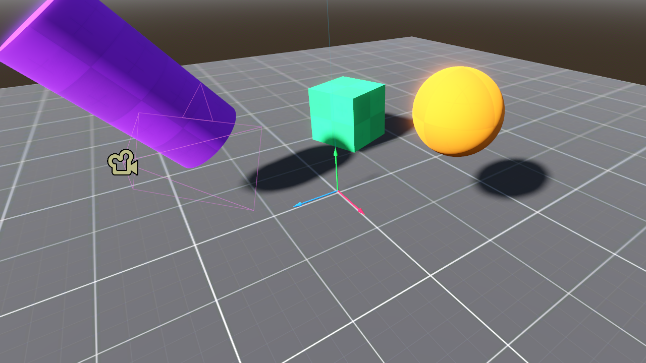
The world
Where the X, Y, Z axis are marked by the red, green and blue arrows. The camera is marked by the little
camera icon and it is looking in the direction of the origin of the world, where the X, Y, Z gizmo is
(it really is called a gizmo). For rendering the whole world is transformed so that the camera becomes
the origin of the world. Every object is moved and rotated so that in the new world, they will have the same
relative position from the camera as they did before.
Might sound a little confusing, but if you look at this picture, it is easy to see that in practice nothing changes, just the camera became the center of everything.
The world with the origin at the cameras position
Then what we would actually see from the camera’s perspective is:
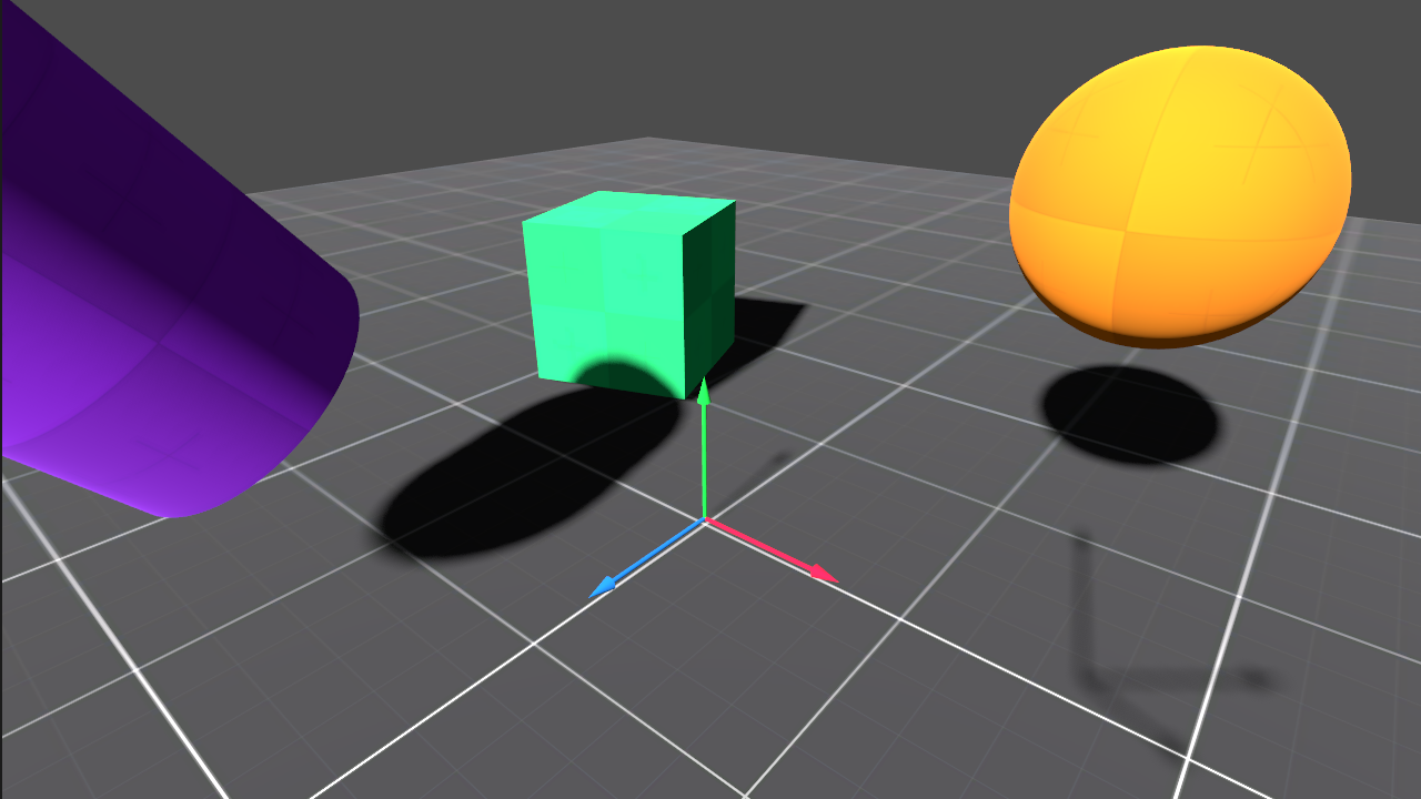
The world from the camera
For clarity, both the world and the camera’s world gizmos are visible. From this point though only the shadow of the camera’s gizmo may be observed.
Why this is done, and how, will be a different post, but had to show it, because it is something you may never know if you haven’t seen how it works.
Engine state
After discussing all the non technical aspects here is the state of the engine: v0.0 (and after all the bugs have been fixed that you will observe below: v0.01)
Reproductions in Godot v0.01 scene v0_0
I have glossed over a lot of details that I don’t think are important for me to duplicate here as they can be seen from the code and are explained better elsewhere.
What has been implemented:
- simple linear algebra library with vectors and matrices
- quaternion based rotations
- all the necessary transformation matrices for the current state, like translate, rotate, scale and the projections
- a simple camera with movement controls copied over from Godot
- a cube, a plane and some basic shader with specular highlights
- a simple directional lamp
- a simple FPS counter using a small ring-buffer for frame time sampling
Most math regarding the transformation matrices and quaternions has been taken from Real-Time Rendering - Fourth Edition. Quaternions are a particularly difficult topic and I had to rely on Rotation Quaternions, and How to Use Them and Quaternion to Rotation Matrix. This later also proved to be very helpful in understanding transformation matrices. Highly recommend it.
While mucking around with an engine one will quickly learn that there is an outstanding level of complexity in the background. Just observe what about 2 weeks of coding and debugging, and at least as much time reading and understanding was able to produce:
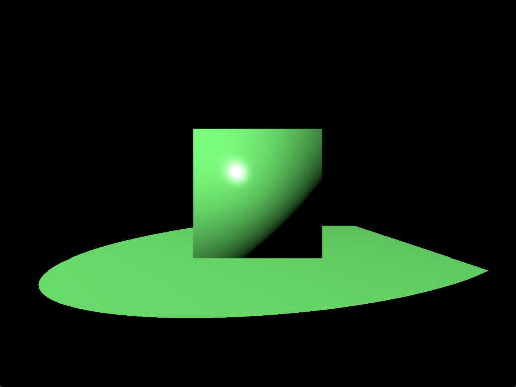
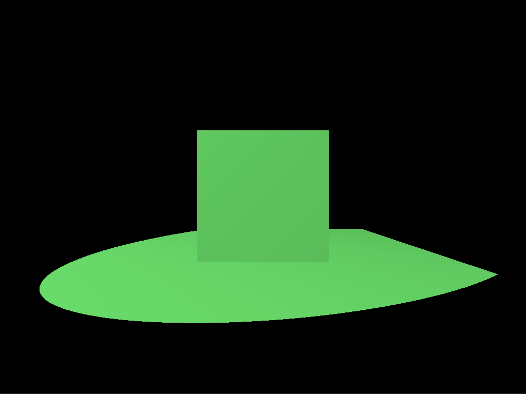
Engine reference
My lord, if there is a heaven, this would surely make the angels cry. What we see is a cube, on a plane, neither with any materials assigned to them. The nasty green is the color of the single spotlight in the scene, which has no falloff at all. All floating in the void of black space. Absolutely marvelous, and humbling in a sense. So much work for so little.
There is a big question that remains though. Is what we see actually correct? How to confirm that? Better yet, how can we confirm in the future if what we do is correct? No easy answer, but there is a reasonably good alternative. Just reproduce the desired scene in Godot. See if that produces the same result.
Godot reproduction
Ehh, it looks rather different doesn’t it? Why can this be? In my short experience, if the image doesn’t look as expected likely some vector or another is incorrect. In this case I happened to remember that to avoid some problems for the cube, in the beginning some tricks were applied. The cube is generated centered at the origo, then each of it’s points is just a unit length position vector from the center. The trick was that I simply used the points as normal vectors as well. Worked okay, but it had this effect where the sides of the cube appear to be curved. This is because along the surface of the cube the normal vectors are interpolated between the vertices. This is such a common technique that WebGPU does this interpolation by default.
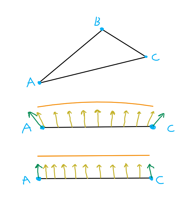
Normals issue
The above demonstrates the suspected issue. We have a triangle with vertices A, B and C. For simplicity let’s look at the triangle so that only the A - C side is visible. With green arrows the normal and yellow the interpolated normal vectors can be seen. In the incorrect setup, the top drawing, the normals are tilted, so the interpolated ones will describe an arc. This arced surface is also highlighted by the orange curve above. The expected outcome is the lower image, where all the normals are completely parallel to one another.
But as we have learned from our lesson, quickly test our theory within Godot, by using the vertex positions as normals and see what we get.
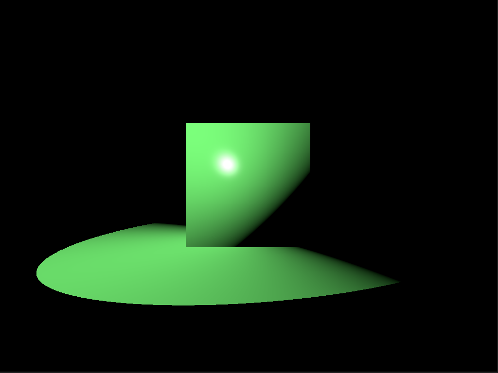
Godot theory confirmation
Excellent, the cube looks exactly as within our engine, with the incorrect normals, so the theory has been confirmed. The plane became different, because in Godot I have only written one shader which is shared between the cube and the plane. This discrepancy can be ignored.
Demo
Finally, at long last, observe the engine in all it’s glory!
FPS counter
To be able to develop any type of decent idea about performance a simple FPS counter has been implemented. Nothing special, just a ring buffer with a 1000 sample slots.
In develop build we get
Avg. FPS: 2743.96
1% low: 1985.52
0.1% low: 1391.16
which is truly rather disappointing for such a simple scene. FPS means frames per second and in general, a steady 60 FPS is targeted for a good experience. It is a good metric for showing how smooth the overall gameplay is, but alone it fails at describing an effect called micro stuttering, during which for just a few frames the FPS drastically drops, leading to perceivable stutter. To be able to measure this the 1% and 0.1% low average FPS counts are introduced as well. They simply answer the question: “What would be our average FPS count if we only took the slowest 1% or 0.1% of the frametimes?” If these values remain close to the average FPS count, we know that the game will be stutter free. To learn more about the topic see Inside the second: FPS & a new look at game benchmarking and What Are 1% & 0.1% Lows?. (Recently there are discussions about FPS Benchmarks Are Flawed: Introducing Animation Error | Engineering Discussion, but I don’t intend to get into that at this time.)
In release build:
Avg. FPS: 11373.37
1% low: 8939.11
0.1% low: 8312.07
The release build looks a lot better. Ten thousand FPS is acceptable, but I have a sneaking suspicion that it should go still a bit faster.
Maybe with Vulkan it could, non the less, based on the data 99.9 % of the frametimes are faster than 120'307 ns, ~ 120 μs or 0.120 ms.
For reference if we were targeting a 60 FPS, our budget for a frametime would be ~16.5 ms.
It will be interesting to see how much certain features will cost in the future.
You may be wondering: “If we have so much FPS why is the demonstration video so choppy?” Well, in truth, not entirely sure yet. I think it has to do with the movements. Just panning is very smooth, similarly with rotation, but if you combine the two it can get choppy. Based on the snippets I have read here an there it is likely, because I don’t use any type of interpolation between the movements. So the sharp change in a direction and/or rotation will appear unnaturally fast.