Idea/goals
At this time I am just learning about electronics and haven’t really built too many circuits. The ones I have made are relatively simple, but they were already easy to mess up, by putting in a transistor in reverse or forgetting to break a connection on the prototyping board. In these cases there is only one thing to do and that is to break out the continuity tester and check the connections while referencing the wiring diagram. A tedious process but the better the equipment the easier and faster it gets.
At the time I was looking for my next project for with the complexity increases a bit. That is when I saw on (https://www.youtube.com/@leosbagoftricks3732) this video about the ultimate continuity tester:
Heureka! Exactly what I was looking for!
Circuit construction
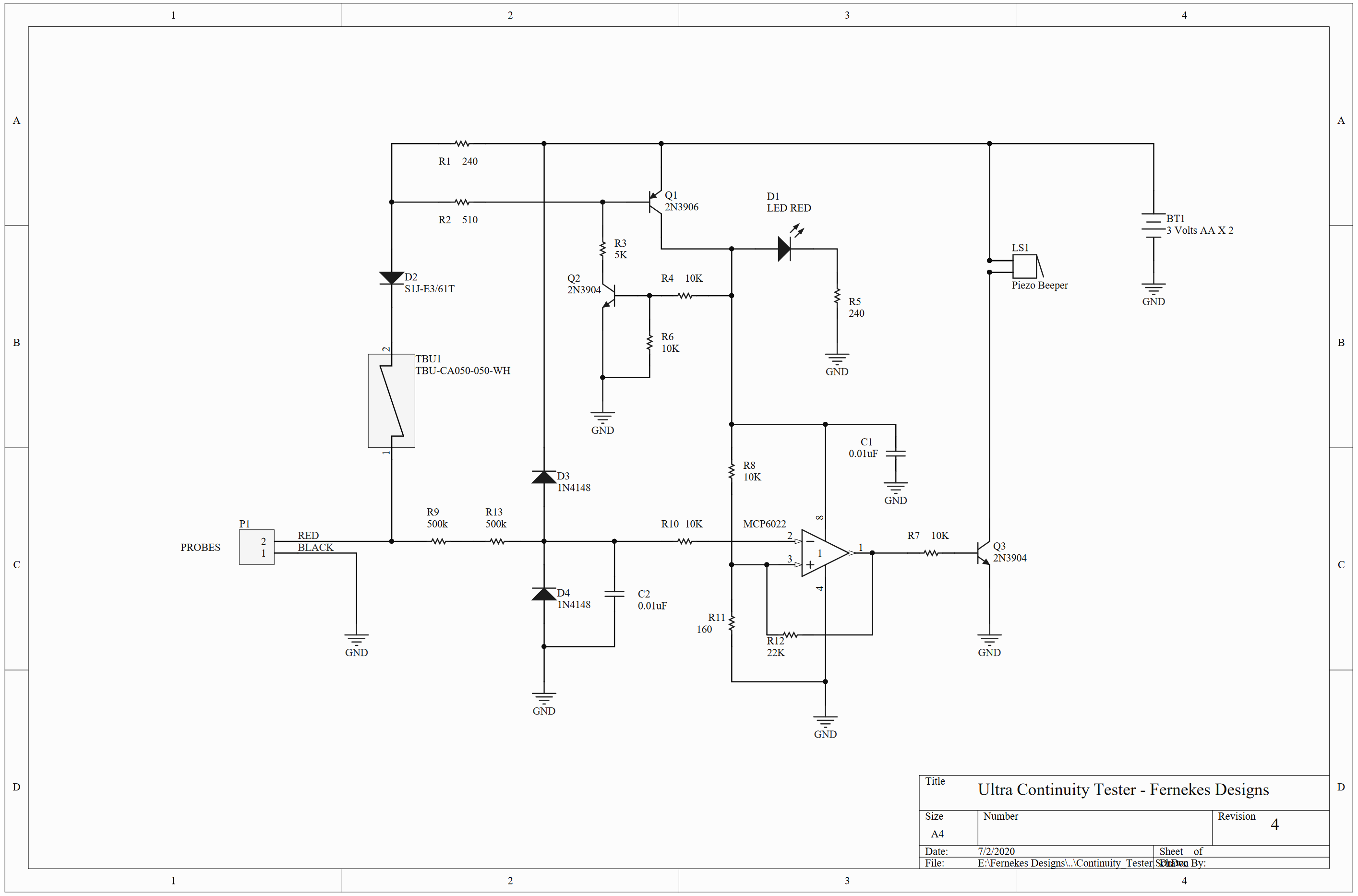
Schematics
Parts
As it can be seen the schematic is not very complicated and the list of parts doesn’t require many exotic components. Nevertheless, as I am not very sure in my skills just yet, I have tried to buy the exact components specified.
The surge protector was a component I have never heard about before, but thankfully it seems to be readily available. For example: TBU-CA065-200-WH. However, it does not seem to exist as a through-hole component only as a surface mount.
Had some trouble sourcing the exact operational amplifier of MCP6022. At the time of the ordering it simply wasn’t available on Farnell, so I have looked for an alternative and choose the LM4562NA/NOPB from Texas Instruments (would have given a Farnell link, but since me buying it, it is no longer listed). Now this is probably a massive overkill, but it is comparable to MCP6022, and it is from a reputable brand. Not sure why we even need a 2 channel op-amp when we only use exactly one of them. Maybe that was the only part available to Leo, maybe some other reason. Nevertheless, I don’t know enough about op-amps to argue, so a comparable one it is.
The beeper was a part that had no additional information, so I wasn’t sure which one to pick. From playing around with such a beeper I know that they need DC and will beep within their specified voltage range. What frequency or sound level to pick though is beyond me, so kinda randomly choose this one ABI-042-RC. It operates between 2-3V range, so at least in that regard it should be perfect for our application.
Finally, the test leads and their connectors took a while to figure out. There seem to be a great number of brands out there with a number of differing sizes. In the end chose a pair of test leads from Tenma (72-9340) and the fitting banana plugs 76-1702, 76-1516.
For all other parts, whenever possible tried to buy through-hole for easier assembly by hand. Don’t have a hot air station and have no idea to etch, fabricate PCBs yet.
Before attempting an assembly I have collected all the necessary parts and ordered them on a piece of paper.
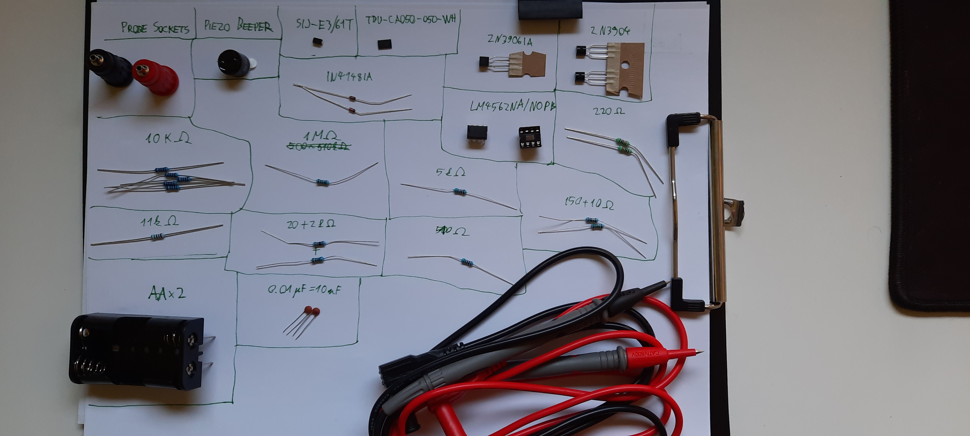
Ordered parts
Now this may seem excessive perhaps, but with my limited experience even such a small circuit seems daunting so a little bit of organization always helps.
In hindsight, it is good that I did this collection, because even with that I have made a mistake and included an 11k resistor for some reason. Also messed up a few resistor values. Don’t quite remember which ones, but if you can read the color codes you may notice it. I have tested all of them before putting them in and at least then noticed that something was a bit off.
Assembly
Really wasn’t looking forward to this. Not sure how to do such assembly well, but for the time being I mostly wing it and just start building the circuit from some point and mostly hope that everything will have its place without too many jumper wires crisscrossing the whole thing (the surefire mark of a botch).
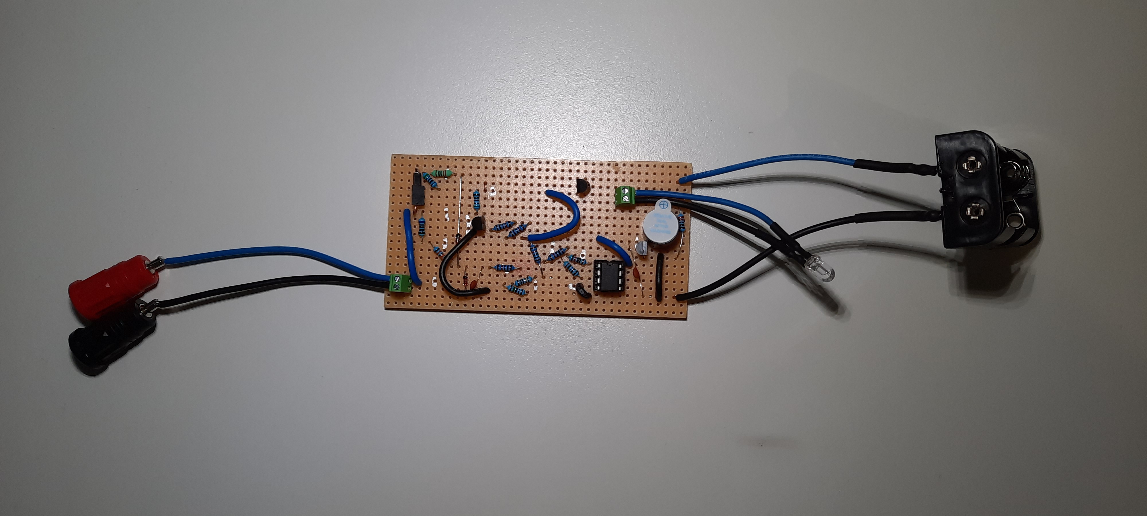
Assembled top
It doesn’t look like much, but it took me about 6-7 hours to assemble it. The tricky part was mounting the surge protector with its diode, which is a surface mount as well. They are simply very tiny, and although they may not seem that small compared to a resistor, since they aren’t through-hole it is very hard to keep them in place while soldering them. Nevertheless, some luck, trial and error and a lot of cursing made it coalesce. Added some tiny solid core pre-bent wires, so they can act like through-holes.
What proved to be useful are the markings on the top where I have signalled in silver paint that a trace needs to be broken. This came very handy, because now I didn’t have to recheck the whole circuit after assembly and figure out which trace should be broken. It was much simpler to mark it right after placing in a component. (The savants among you may have spotted, that I have missed connecting the cathode for the little buzzer. That was easy to fix later though.)
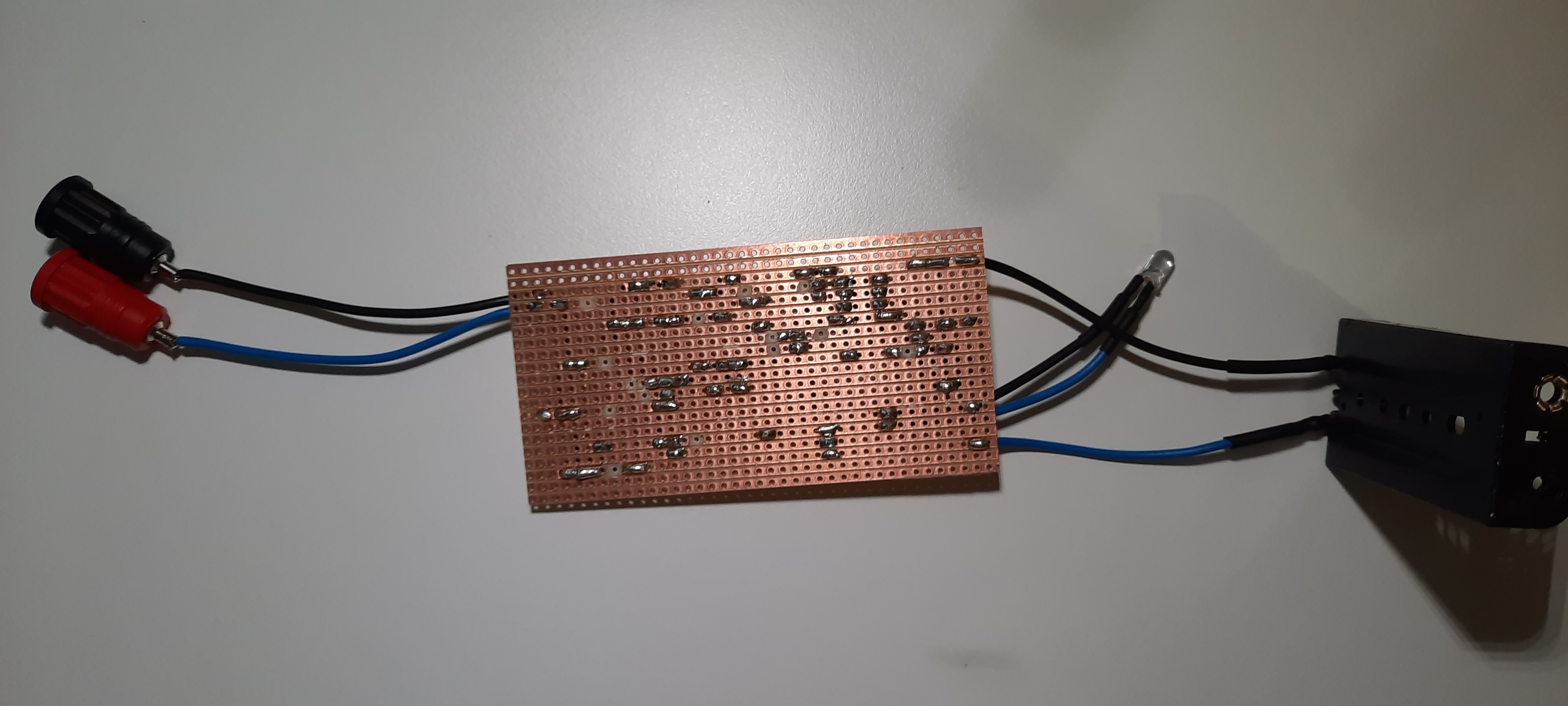
Assembled bottom
Testing
Not gonna lie, this part was rather tense. I was nearly certain it won’t work, at least not on the first try. Messed up simpler circuits before, so I was very surprised when it actually worked! Except for the previously mentioned little buzzer cathode connection being amiss, everything seemed to be okay. However, I had to do one final test as well, connecting the probes to live and hoping that the surge protection works as it should. Tested that as well, and heard the soothing frying sound as in Leo’s video! Yay, no magic smoke tonight!
Housing construction
Designing the housing is always one of the tasks that seems easy at first, but then takes a long time, and it will get messed up anyway. Nevertheless, after designing a few housings already I have understood 2 things. Try and measure everything in advance and have a general idea of what are you going to make, if manageable with exact dimensions. Don’t skimp on time and try and model each part of the project so that while designing you can have an immediate feedback about spacing/fitting/layout. The first one can speed up the initial modelling stage, but the second one can save you model iterations, which can mean days.
Design
The idea was simple. Make a box from two components. The top one should be a single piece as it will be user facing, ensuring that it will come out of the printing process looking much better as there will be no parts to join together. The bottom part should be a simple sliding panel, and it will be held in by a grove.
The banana plug inserts will be glued in as there was really no other option for the specific plugs I got. They lacked any kind of built-in mounting mechanism. The battery compartment can dangle anywhere as long as its cables allow for its placement. All of this has left only the question of securing the PCB inside the housing. In this regard I only had the foresight, before assembling the PCB to leave an about 3 mm gap free of any component on each of the longer sides of the PCB for mounting purposes. Had no idea how that mounting would look like though. At this point it seemed like a good idea to experiment with M3 screws. I had a number with 16 mm length, had short little inserts for them as well, so my idea was to simply make 4 channels for the screws where the inserts would be put and by threading in the screws, their heads would secure the board to the top part of the container. Even had the idea to put in a little relieve channel where the screws can be oriented properly before being threaded in, making assembly easier.
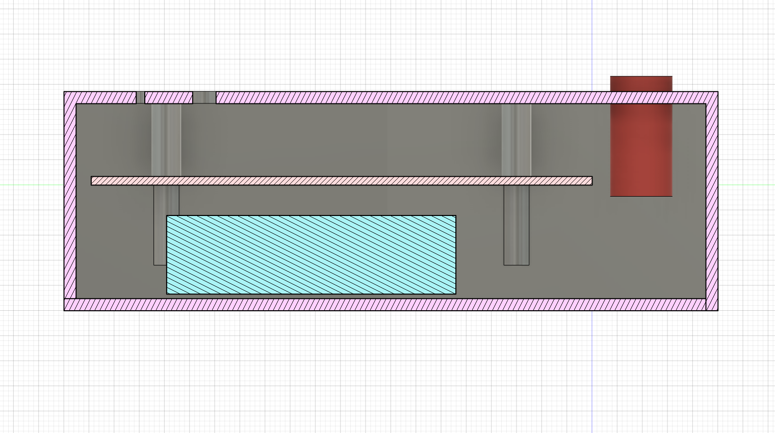
Housing design, section analysis side
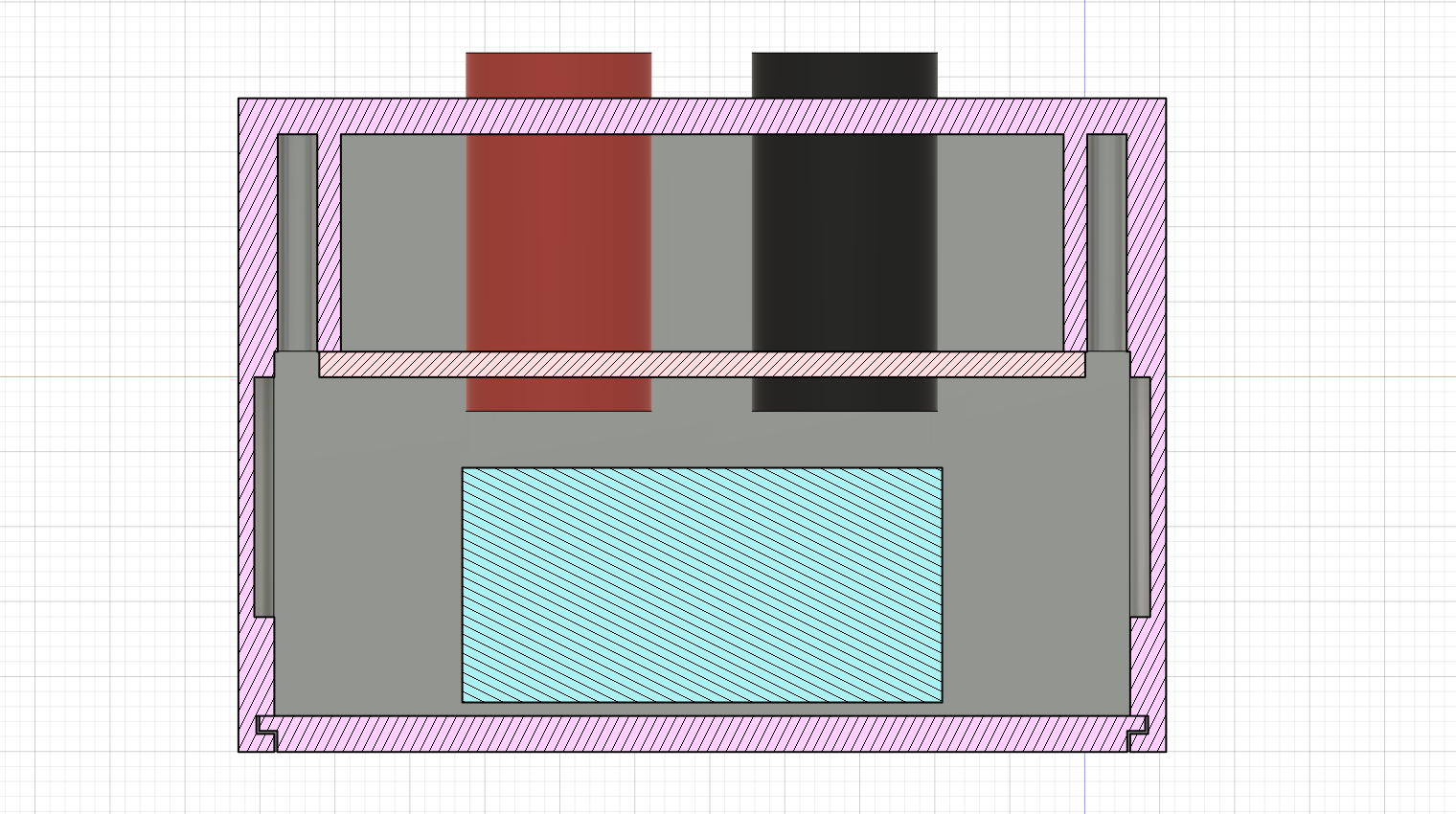
Housing design, section analysis back
Housing assembly
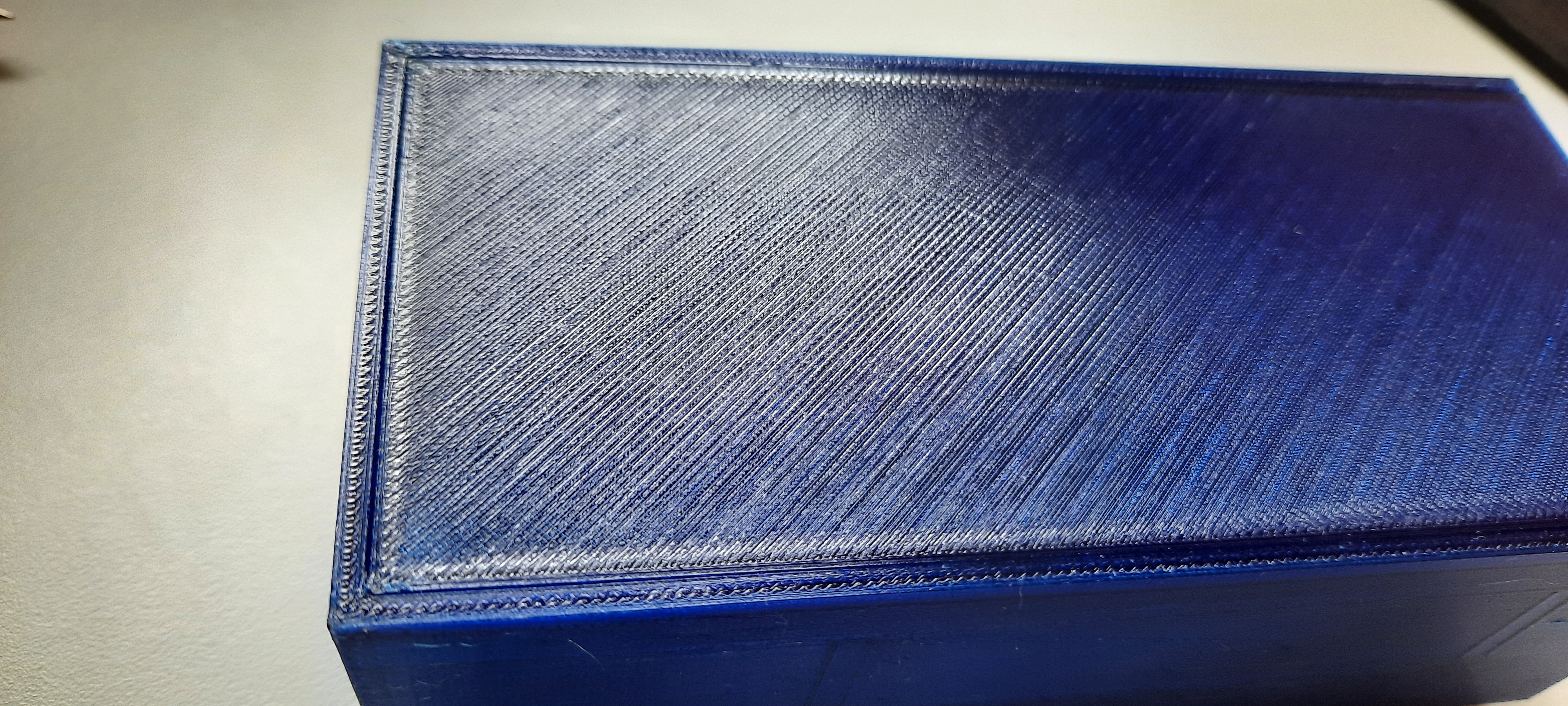
3D printed the top compartment using PETG with a 0.4 mm nozzle in about 6.5 hours. Then put in the inserts …
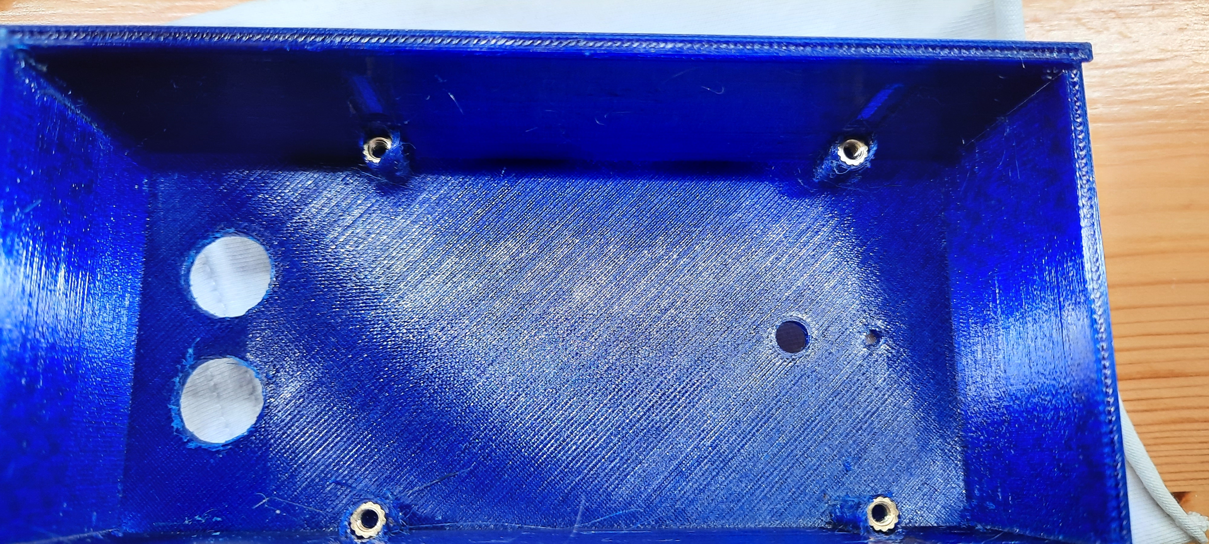
Housing top with inserts
… and I forgot about 2 things. To size the hole for the insert properly I should have measured the skirt part of the insert instead of the thread diameter of the M3 screw. The holes for the inserts were now slightly too small, and even though they can be easily melted in with a soldering iron, they push in the melted material in front of them. The result? A nice thread into which not much can be threaded into after the depth of the insert as it will be filled in with molten plastic. Now I had the option of cutting down all my 16 mm long screws to about 4 mm in length or use the tinkerers second super weapon after duct tape, hot glue.
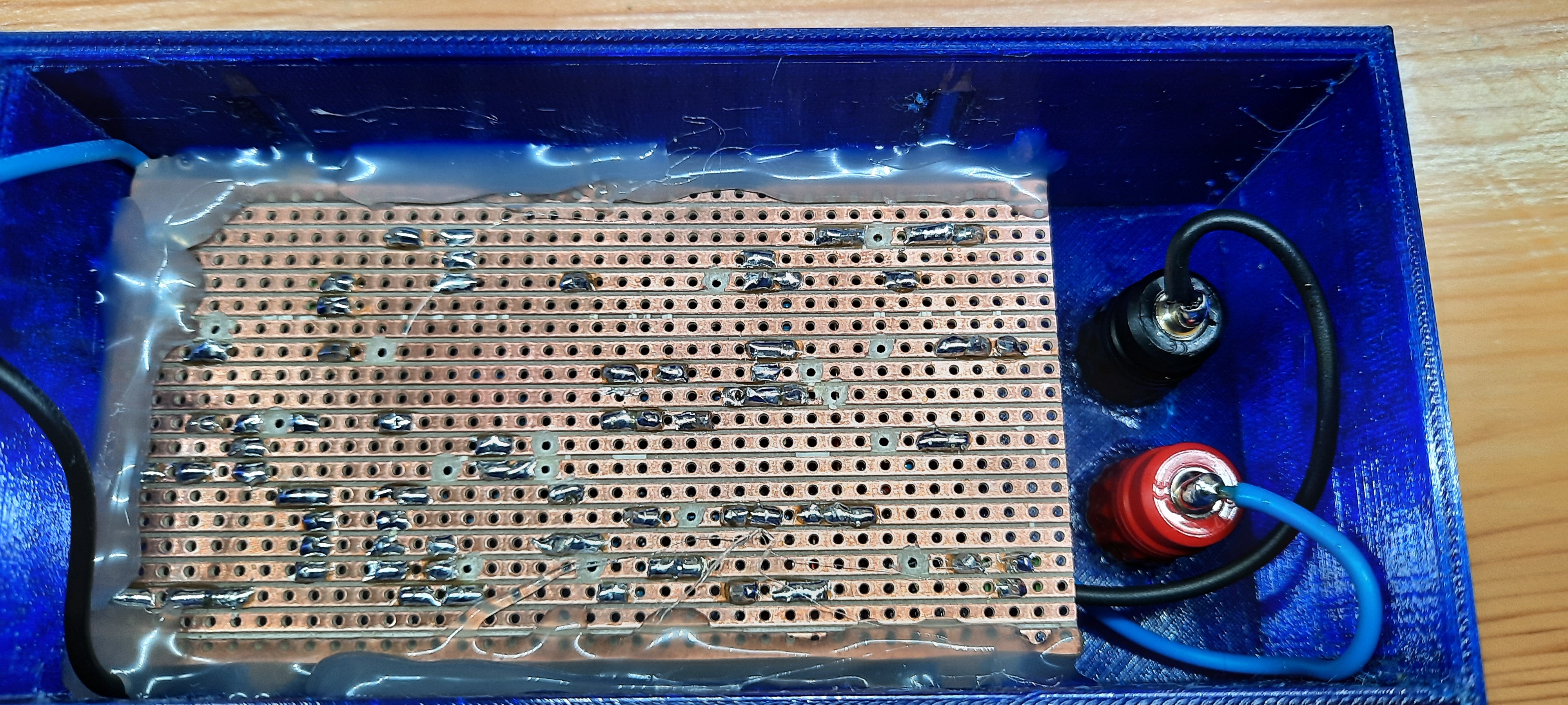
Hot glue works
It doesn’t look good, but it will serve. Anyway nobody is going to look at the insides.
During this hot glue assembly the wire to the red banana plug broke off, so I was a bit worried that maybe something else broke too. Thankfully after resoldering the wire and doing a quick test everything was still okay.
Well okay, I may not be able to use inserts properly, the bottom panels sizing was spot on. With the 0.4 mm tolerance accounted for the panel slides in and fits snugly.
Bottom fit
Finished
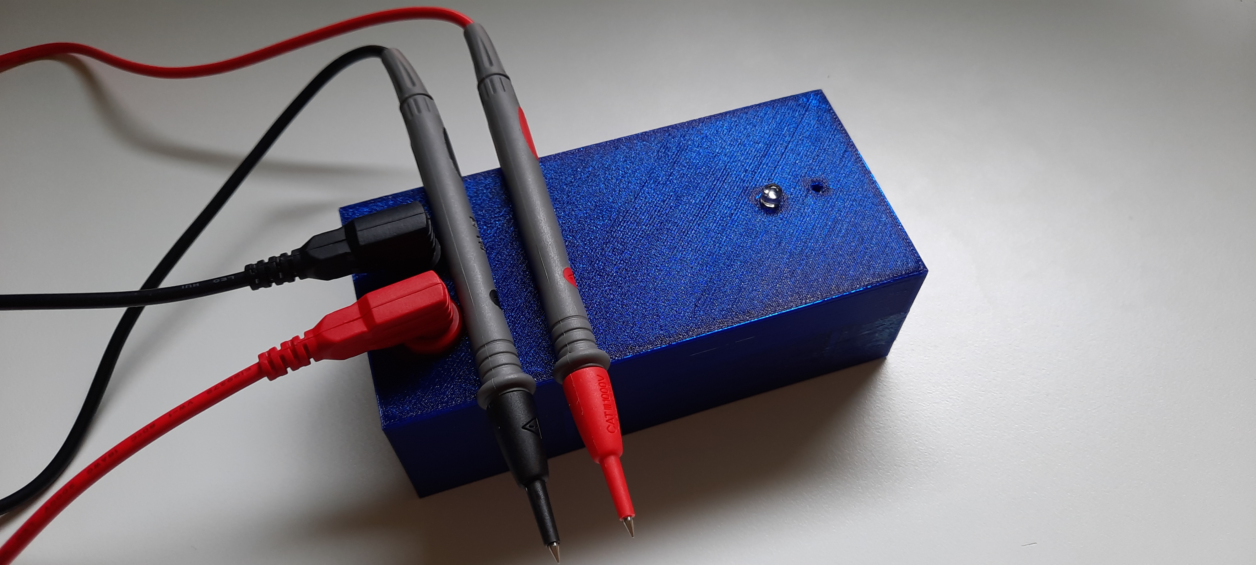
Complete
The final product looks decent, and these probes are better quality than the ones I have for my regular multimeter. As a plus it still works too! Hmm, maybe next time I should try to simplify the parts list and manufacture and assemble a proper PCB for it, like it was done by another tinkerer here: Rambling-X
Files
Fusion 360 link: continuity_tester